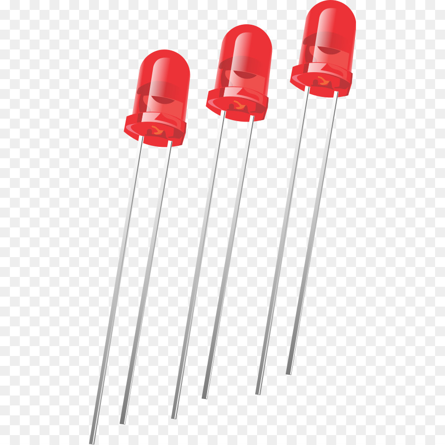
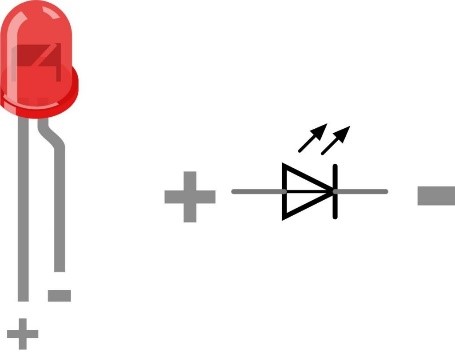
LED:
Application:
Raspberry Pi:
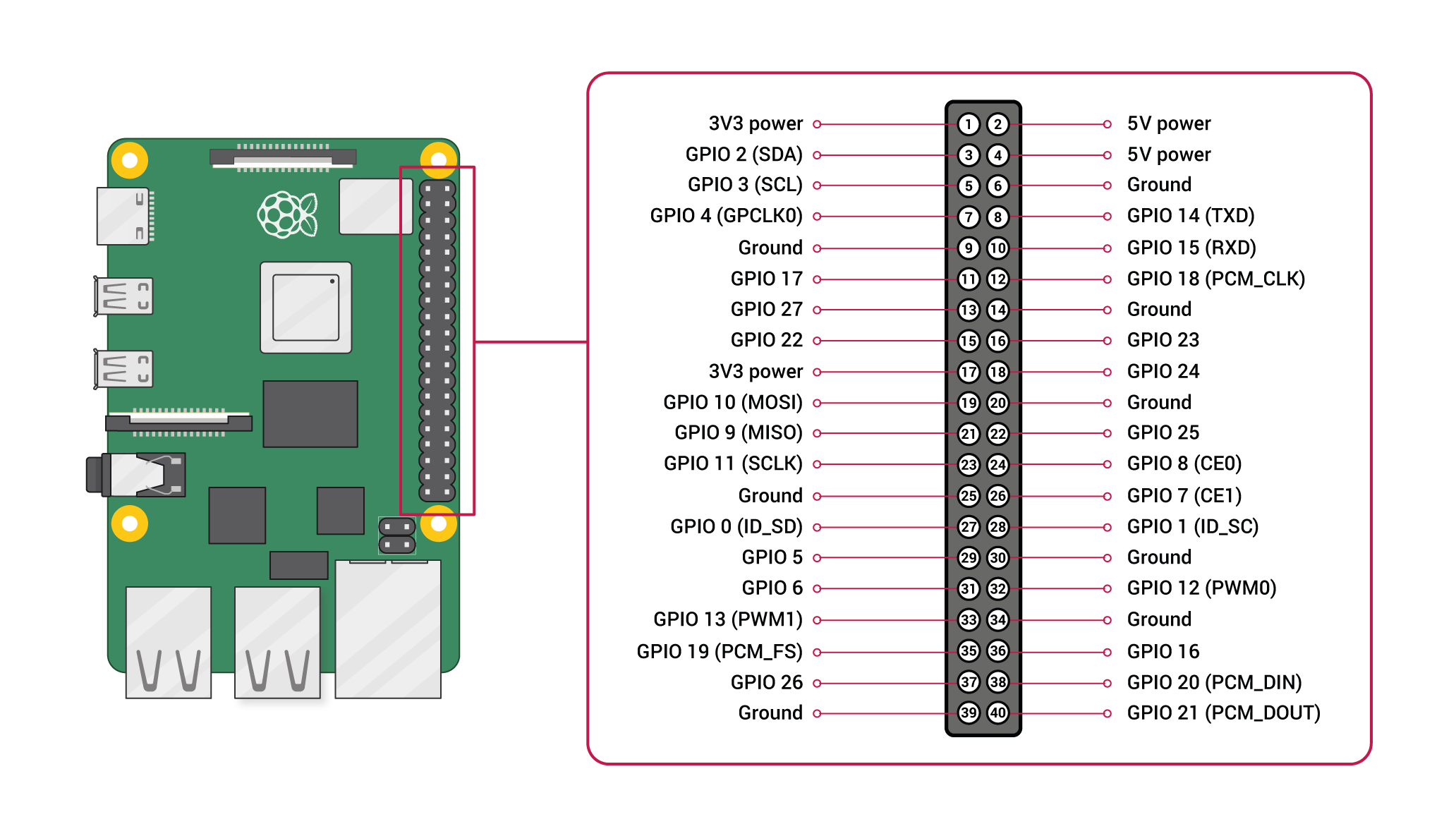
Pin configuration:
1. Vin: Two 5v pins and two 3v3 pins used for providing power supply, where processor works on 3.3v.
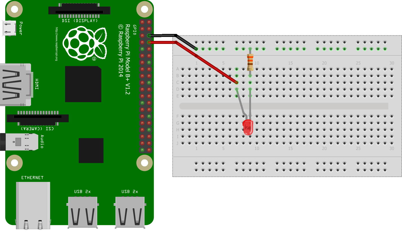
import RPi.GPIO as GPIO
import time
GPIO.setmode(GPIO.BOARD)
GPIO.setup(8, GPIO.OUT)
while True:
	GPIO.OUTPUT(8, GPIO.HIGH)
	time.sleep(1)
	GPIO.OUTPUT(8, GPIO.LOW)
	time.sleep(1)